24th Edition Support
-
This web page is for information that extends or supports the ARRL Antenna Book, 24th edition. The section for each edition contains links to supplemental files and software, non-ARRL documents, and errata and corrections.
Supplemental information is available as a downloadable package beginning with this edition. You will find an access code on a sheet inside the front cover with complete instructions. Once installed, use Adobe Reader to access the PDF files. See the Software folder for HFTA angle-of-arrival files if your installation did not produce a complete, world-wide set of files.
The installation software will create Desktop shortcuts - they will all have the same ARRL-diamond icon and the names will all begin with "ARRL Antenna Book" so it can be hard to tell what each of the shortcuts activates. Holding your cursor over the shortcut will expand the name to the full name. Or you can rename the shortcuts by right-clicking on the shortcut and selecting Rename. One suggestion is to use names like "AntBk Contents", "AntBk Suppl", "AntBk SWare", and so forth.
Some readers report that the version Adobe Reader Touch, provided with Microsoft Apps, does not support all of the PDF features. If this is a problem, download the free Adobe Reader DC from the Adobe website at get.adobe.com/reader which does support the necessary elements, such as bookmarks. Note that the website for downloads will also download a Google Chrome extension and two McAfee security applications unless you opt out by unchecking the necessary boxes.Printed-circuit boards for many current and previous Antenna Book projects are available from FAR Circuits.
PREVIOUS EDITIONS
Information in support of previous editions can be found on the ARRL Antenna Book - 23rd Edition or ARRL Product Notes page for editions before the 22nd.
-
Installing and Running HFTA, TLW, and YW
The programs HFTA, TLW, and YW are known to have difficulty running on 64-bit versions of Windows operating systems. They were developed for and run on 32-bit versions of Windows operating systems. If you experience problems, try the "Run as Administrator" option when starting the program. There are no plans to update the software.If you are unable to install the software from a CD-ROM, transfer the file to a flash drive and then install it from the flash drive. It may also be possible to copy, not install, the file to the computer's hard drive and then install it from the hard drive but the flash drive approach has been the most reliable option.
SCALE and MAKEVOA
These are MS-DOS programs and will not run under current versions of Windows. The emulator program DOSBox can be used to run old MS-DOS programs on new computers. It is an emulator designed to run old computer gaming software.
The following PDF instruction files are provided here as a convenience to users of the software provided in the Antenna Book downloadable supplemental information.
HFTA - Instructions
YW - Instructions
TLW - InstructionsThe package of angle-of-arrival files created by Dean Straw, N6BV, in support of HFTA terrain analysis may have been partially installed or omitted entirely. The entire package, including antenna models, is available as a downloadable zip file at the following link:
Microdem is no longer able to access the national data files. To obtain terrain profiles, go to k6tu.net and generate the files using the online interface to access the locally stored data.
EZNEC - previous editions of the Antenna Book included a version of EZNEC-ARRLwhich ran special model files. This software has been replaced by the demo version of EZNEC 6.0 which available online from the EZNEC website. The demo version of EZNEC will run the EZNEC-ARRL models without modification.
The following list includes Windows-based software utilities that support various topics in the Antenna Book. Chapter numbers refer to the primary chapter in the ARRL Antenna Book that references the software. No additional documentation is available beyond what, if any, is provided with the software.
Unless otherwise noted, all of the software listed here can be downloaded to your hard drive, unzipped if necessary, and run directly from the Windows Start menu without requiring installation in the Windows system.
Chapter 1 - Antenna Fundamentals
SCALE.ZIP - a software utility to change the frequency of YW antenna models while compensating for element diameters and taper. Models from other software can be used as described in the documentation included with the utility.
Chapter 4 - Radio Wave Propagation
RngBrg.ZIP - software to compute the range and bearing from a point at one latitude/longitude to another.
Chapter 6 - Multielement Arrays
Arrayfeed1.zip - this is a link to software by W7EL to design feed systems for phased array using transmission lines. There are three files - a readme file, a help file (.chm), and the program itself (.exe). Previous editions contained an incomplete ZIP file that omitted the .exe file. All three elements of the program may be downloaded from the author's website.
SCALE.ZIP - see Chapter 1 above.
ARRL-EZNEC Phased Array files - these files are referenced in the array design section by Roy Lewellan, W7EL and were mistakenly omitted from the download package for the book.
Chapter 7 - Log Periodic Antennas
Log Periodic Element and Phase Line Calculator - Spreadsheet to calculate LPDA element lengths and spacings, along with phase line impedance, by Dennis Miller, KM9O. This spreadsheet is in Excel format (XLS) and was last updated on 12 Sep 2011.
Chapter 11 - HF Yagi and Quad Antennas
GAMMAMW4.ZIP - An improved version of the previous utility GAMM2-1 that corrects a calculation problem that fails to find solutions to the calculations when the combination of the desired feed line impedance exceeds the product of the raw antenna resistance and the gamma step-up value. The code was developed by Bill Wortman, N6MW and generously donated to the ARRL and the readers of the Antenna Book, ARRL Handbook, and Low-Band DXing by ON4UN. The ARRL also wishes to thank Greg Ordy, W8WWV for testing the code.
EFFLEN.ZIP - A software routine (written in FORTRAN) to calculate effective lengths of antenna elements.
Chapter 21 - Mobile and Maritime HF Antennas
MOBILE.ZIP - Mobile whip design software by Leon Braskamp, AA6GL. The compressed file includes MOBILE.EXE - the software - plus a desktop icon file.
Chapter 23 - Transmission Lines
Two-Wire Feed Line and Radiated Power Calculator - Spreadsheet to calculate the impedance of parallel-conductor line and the amount of radiated power by Dennis Miller, KM9O This spreadsheet is in Excel format (XLS) and was last updated on 12 Sep 2011.
AAT.zip - software to analyze antenna tuners by Dean Straw, N6BV. The compressed file includes AAT.EXE - the software - plus a PDF instruction file, desktop icon, and associated LOG and SUM file examples. The program will not run under 64-bit operating systems. The program has been run successfully under versions of Windows that have 32-bit/16-bit compatibility, such as XP and Vista. It will not run under 64-bit versions of Win 7/8/10.
The concept of impedance matching is explained by Lou Ernst, WA2GKH in a two-part tutorial "Load to Source Matching". The tutorial consists of a text-and-figures presentation explains the concept and process. The presentation is accompanied by an Excel spreadsheet that allows the student to experiment and observe the effects of matching.
Chapter 26 - Building Antenna Systems and Towers
Hal Kennedy, N4GG, constructed a simple Excel spreadsheet to calculate the clearance between Yagis and guy wires on a guyed tower. Calculations are simplified by the assumption that all guy wires, booms, and elements are straight (no sag).
SUPPLEMENTAL INFORMATION AND FILES (31 AUG 2020)
Supplemental Files Directory - a searchable PDF list of articles and other documents provided with the Antenna Book in the downloadable supplemental information.
Project Directory - a PDF list of projects in the Antenna Book, sorted by project type.
Radio Mathematics - a compilation of math basics and online resources in case help is needed with math encountered in the Antenna Book. (Also included in the downloadable supplemental information.)
Antenna Modeling Programs
This table by Steve Stearns, K6OIK, from the Antenna Modeling chapter (Chap 8) of the Antenna Book's 24th edition lists a number of antenna modeling programs based on the NEC2 computing engine along with electromagnetic solver/modeling/simulation programs. The professional programs may have student or non-commercial versions available at lost cost. The modeling programs are generally low-cost and some are free. Reviews of the software may be available on websites such as eham.net.
K6OIK has also published "Antenna Modeling for the Radio Amateur" - a PDF version of a Powerpoint presentation last updated in 2016. It covers a lot of background and has many links to other tutorials and references. Excellent for the reader interested in knowing what other techniques and tools are available.
ARRL antenna modeling files for the ARRL Antenna Book - the set of EZNEC modeling files represent many of the antennas discussed in the Antenna Book. The models are grouped in folders named for the type of antenna they represent. A complete description of the files is included on this README.TXT file which is duplicated in the book's downloadable supplemental information. The models include the new high-performance VHF/UHF Yagi designs by GØKSC created for the 23rd edition of the Antenna Book and discussed in Chapter 15. The GØKSC models require EZNEC/PRO4 for accurate reproduction of the radiation pattern, gain, and other specifications.
K1FO VHF/UHF Yagi designs from previous editions are provided as a PDF document in the book's downloadable supplemental information.
Chapter 11 - HF Yagi and Quad Antennas
Rich Haendel, W3ACO, had updated his two-element 30 meter Yagi design originally published in the QST article “Build the Two Element 30 Meter Beam” in the August 2013 issue.
1. I changed the taper schedule so the elements have less droop.
2. I simplified the feed connection to make it easier to build. Instead of the original transformer feed, the coaxial feed line cable is now connected directly to the driven element. An impedance match is achieved by connecting a 0.6 µH shunt coil across the driven element terminals. Ten ferrite beads using #73 ferrite material 0.5” ID, 1.0” OD, 1.25” long, were placed on the coax along the boom. (See the ARRL Antenna Book chapter on Transmission Line System Techniques for alternative ferrite-core choke balun designs.)
3. Given that the 30 meter band is fairly narrow, it is important to follow the element taper schedule closely. For example, in a recent build, the initial minimum SWR point was at 10.095 MHz. To re-center the minimum SWR point at 10.125 MHz, each of the four element tips needed to be shortened by 1.0 inches on BOTH the driven element and the director. Antenna SWR tests were made at the base of the tower through a 65-foot length of BuryFlex. The shift in frequency can be simulated in the model, as well: a 1.0-inch change in element tip section length shifts the frequency of minimum SWR by 30 kHz up (shortening the tips) or down (lengthening the tips).
An zip file with the updated EZNEC model file, W3ACO 30M Yagi – Revised.EZ, is also available.
Chapter 16 - Mobile VHF and UHF Antennas
Dave Patton, NN1N, notes that to avoid scratching the paint under a mag-mount antenna, cut Tyvek (thin, tough plastic film) circles that are the same diameter of the magnets. Place the film under the magnet and the mount will still stay firmly attached without affecting the electrical characteristics. (The same goes for HF mobile mag-mount antennas.)
Chapter 22 - Receiving and Direction-Finding Antennas
Gary Johnson, NA6O, contributed this nice construction article for a useful project, "Handheld Direction Finding Loop Antenna for RFI Location".
Chapter 24 - Transmission Line System Techniques
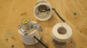
Glen Brown, W6GJB, contributed a photo of how to attach an SO-239 to a 3/4-inch PVC end cap: "You have to hunt around to find 3/4-inch PVC end caps with flat ends - most are domed. Drill a 3/4-inch hole for the SO-239. Solder the lug unto the connector with #6 self-tapping screws before screwing to the PVC cap. Bring the wire to the center pin out the side leaving enough room inside the cap to insert either pvc pipe or reducer."
You can find more of Glen and Jim Brown, K9YC's choke designs in this chapter.
-
Errata and Clarifications (29 APR 2022)
Contributors
Ron Block, NR2B was misidentified in the Chapter 26 Bibliography - his name is correctly "W. R. Block".
Chapter 1 - Antenna Fundamentals
At the end of section 1.3.6, a paragraph is repeated from earlier in the section and can be disregarded.
Chapter 2 - Dipoles and Monopoles
On page 2.4, the third paragraph's beginning sentence, "As a horizontal dipole is brought closer to ground..." should read "As a horizontal dipole is brought closer to ground from free space..." The intent is to explain that ground reflections combine with the direct radiation to form the more complex pattern. A similar process occurs as the antenna is raised from a very low height: the omnidirectional, single-lobe pattern breaks up into multiple lobes as shown in Figure 2.5.
Chapter 3 - The Effects of Ground
In Table 3.1, the column headings are incorrect. The first column is Dielectric Constant, the second column is Conductivity (S/m), and the third is Relative Quality.
Chapter 4 - Radio Wave Propagation
On Page 4.5 (upper left) the suggestion is made, "This also suggests that a station using a circularly-polarized antenna will have a 3 dB advantage over a station using a linear-polarized antenna (horizontal or vertical)." That is not quite correct - the station must be able to switch between right- and left-handed polarization.
If the polarization of the electromagnetic wave exiting the ionosphere is circular, it can be right-hand circular (RHCP) or left-hand circular (LHCP) depending on which way the tip of the polarization vector is rotating – clockwise or counterclockwise. Since these two polarizations rotate in opposite directions, a circularly polarized antenna at a station needs to be able to switch between RHCP and LHCP to couple to whichever circular polarization is prevalent at the moment.
Thus, it would be more correct to say, "This also suggests that a station using a circularly-polarized antenna will have a 3 dB advantage over a station using a linear-polarized antenna (horizontal or vertical) if the down-coming polarization is circular. But the circularly-polarized antenna must also be able to switch between right-hand and left-hand circular polarization to couple to whichever polarization is prevalent.” (Thanks to Carl Luetzelschwab, K9LA for the updated explanation.)
Chapter 6 - Multielement Arrays
In equations 3 through 6 on page 6.11, all references to radiation resistance should be Rr.
Chapter 8 - Antenna Modeling
The modeling reference list includes the out-of-print book Antenna Modeling for Beginners. This book has been replaced by An Introduction to Antenna Modeling which is an RSGB publication based on the free MMANA modeling program.
Chapter 15 - VHF, UHF and Microwave Antennas
On page 15.51, equations 6 and 7 show a variable, C-sub-1, that should be C-sub-λ (lambda). The variable represents a circumference of one wavelength. C-sub-λ is defined on the previous page at the bottom of the first column. The error is due to an improper conversion by print preparation software of the Greek letter λ to the Latin lower-case L which looks like a numeral 1. The variable appears to be shown correctly elsewhere.
Technology >> ARRL References >> ARRL Antenna Book Reference >> ARRL Antenna Book 24th Edition


